IoT Hacks for IoT geeks. http://iot-hacks.com

Webcam Streaming with LinkIt Smart 7688

8:32 PM Posted by Gopal Lal 3 comments

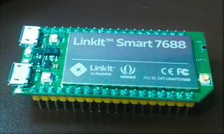
LinkIt Smart 7688

Hello and welcome friends. Today we are going to connect a webcam to LinkIt Smart 7688 device and streaming it on HTTP port with help of 'mjpg-streamer'. So let's start.

So what we need:
  • LinkIt Smart 7688 Board,
  • a USB Webcam. I am using Logitech's 270,
  • a USB OTG cable,
  • a computer or laptop with wifi connection,
  • and a wifi network.
The first step is to connect the LinkIt Smart to your wifi network. If you don't know how to connect the check it here

Now login to LinkIt Smart through ssh.
ssh root@mylinkit.local

Make sure the LinkIt Smart has 'mjpg_streamer' package installed. Type the following command. It will give you details about the package.
mjpg_streamer -h

If your device doesn't have this package then install it with 'opkg install' command.

Now run the following command.

mjpg_streamer -i "input_uvc.so -d /dev/video0 -r 640x480 -f 25" -o "output_http.so -p 8080 -w /www/webcam"

 This will stream your webcam to HTTP port 8080.


MediaTek LinkIt Smart 7688 - Get started

6:42 AM Posted by Gopal Lal 1 comment
MediaTek LinkIt Smart 7688 is a powerful platform for IoT applications. The heart of the platform is the MT7688AN SOC. This chipset is based on a powerful 802.11n 1T1R Wi-Fi AP, supports up to 2Gb RAM with additional SD-card storage, encryption engine Wi-Fi and a wide variety of peripheral connectivity options.  Know more about LinkIt Smart here.
Let's get start with LinkIt Smart. The basic connectivity of device is shown here. The device has to USB ports, two indicator LEDs and two reset buttons. To power up the board, connect one end of micro USB to the power connector of the LinkIt Smart board and another end to your computer or other 5V power source.  The Power LED (Green) will light up first, followed by the Wi-Fi LED (Orange) which will blink once. Then, after about 4~5 seconds, the Wi-Fi LED will light; this indicates that the boot loader has initialized. After the boot loader has initialized the boot up process begins, which takes about 30 seconds. Next, the Wi-Fi LED turns off; this means the system is ready to accept a Wi-Fi connection.

Connect to LinkIt Smart 7688 with web UI:
After the boot process is completed the wi-fi access point of LinkIt Smart will on. Now connect your computer or laptop to this access point. Search for the LinkIt_Smart_7688_XXXXXX Wi-Fi access point (XXXXXX is the MAC address) and connect to the board. Now open http://mylinkit.local and you will get the Web UI of LinkIt Smart 7688. Since LinkIt Smart uses mDNS so in windows 7 or earlier you may need Bonjour.
On first time access to the Web UI, you will be asked to set a password as shown in the figure. Please remember your new password, next time it will be required.
Access the System Console of 7688 board:
  • For Windows: 
      • Open PuTTY and in the configuration window, type mylinkit.local in Host Name, select SSH and click open.

      • The PuTTY terminal window displays. Sign in with the username root and the password you set previously in the Web UI. After sign in you should see a screen similar to the one below.  
    • In Mac or Linux:
      • Open Terminal and at the command prompt type ssh root@mylinkit.local. Press return and enter the password you set previously in the Web UI.

        If you see a warning error indicating host ID has changed, please check the Troubleshooting section in the MediaTek LinkIt Smart 7688 Developer’s Guide.

        You now have access to system console using SSH. You can move on to running your first application on the LinkIt Smart 7688 development board.  For more details visit here.
      Now you can use the LinkIt Smart as wifi station.
    • To do this login to web UI and click on 'Network' button on right side.

    Select 'Station Mode'.
    Now select your access point and enter the password.
    Next click on  'Configure & Restart'.

    This will reboot the system and our board will be in station mode. The reboot process will take some time. Once the reboot process is completed the board will be connected to the network you selected. Now connect your computer or laptop to the same network. Once connected you can access LinkIt Smart 7688 with host 'mylinkit.local'.

    Analog Input Pins

    11:24 PM Posted by Gopal Lal No comments
    The Atmega controllers used for the Arduino contain an onboard 6 channel analog-to-digital (A/D) converter with 10 bit resolution (0-1023). The main function of the analog pins is to read analog sensors, but analog pins also have all the functions of digital pins (pin 0 to pin 13).

    Digital Pins of Arduino

    7:09 AM Posted by Gopal Lal No comments
    The digital pins on the Arduino can be configured as either inputs or outputs. These pins works on HIGH(5V) and LOW(0V) states but some of them also works as PWM pins (We will talk about PWM in upcoming posts). There are 20K pullup resistors built into the Atmega chip that can be accessed from software. We will discuss

    Blink an LED with Arduino UNO

    12:08 AM Posted by Gopal Lal No comments
    Blinking of an LED is continuously changing the state of led that's mean to On and Off. Since the Arduino has its pins high at 5V and low at OV so it easily can drive an LED. Lets start with the circuit. Here is the systematic of the circuit made on  Proteus ISIS.

    I have connected the LED to pin 13 and a resistor of about 220 Ohm is connected in series with led and the connected that to ground.

    Getting Started Programming with Arduino IDE Software

    11:19 PM Posted by Gopal Lal No comments
    Arduino IDE is the software to program the Arduino board. First you have to download the software from arduino website. You can simply download it from here. Choose your suitable version. Now you have to install this software in your computer or laptop. 
    Programming with Arduino IDE
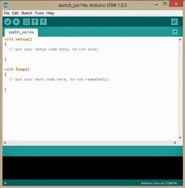
    The basic sketch of Arduino IDE is looks like this. 

    The sketch has two main parts:-

    Arduino Uno

    11:16 AM Posted by Gopal Lal No comments


    The Arduino Uno is a microcontroller board based on the ATmega328. It has 14 digital input/output pins (of which 6 can be used as PWM outputs), 6 analog inputs, a 16 MHz ceramic resonator, a USB connection, a power jack, an ICSP header, and a reset button. It contains everything needed to support
    the microcontroller; simply connect it to a computer with a USB cable or power it with a AC-to-DC adapter or battery to get started.